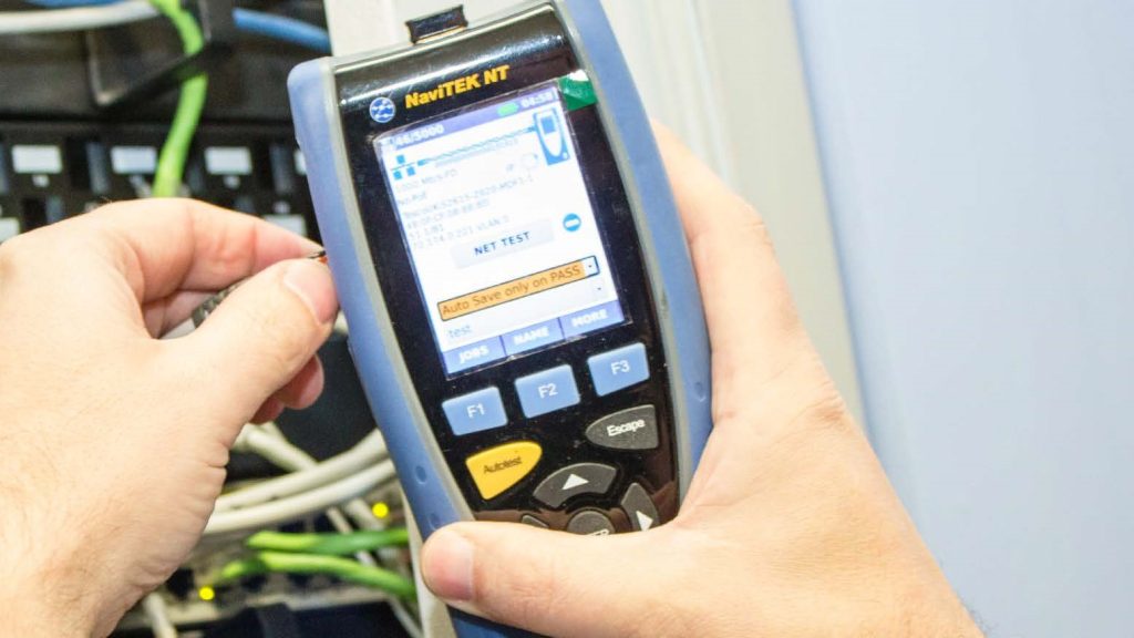
FIBERTEK IV – FIBRE CERTIFICATION ADAPTERS FOR THE LANTEK IV-S
For fast and simple fibre optic cable certification
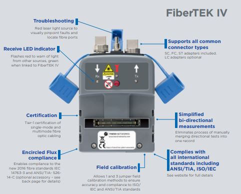
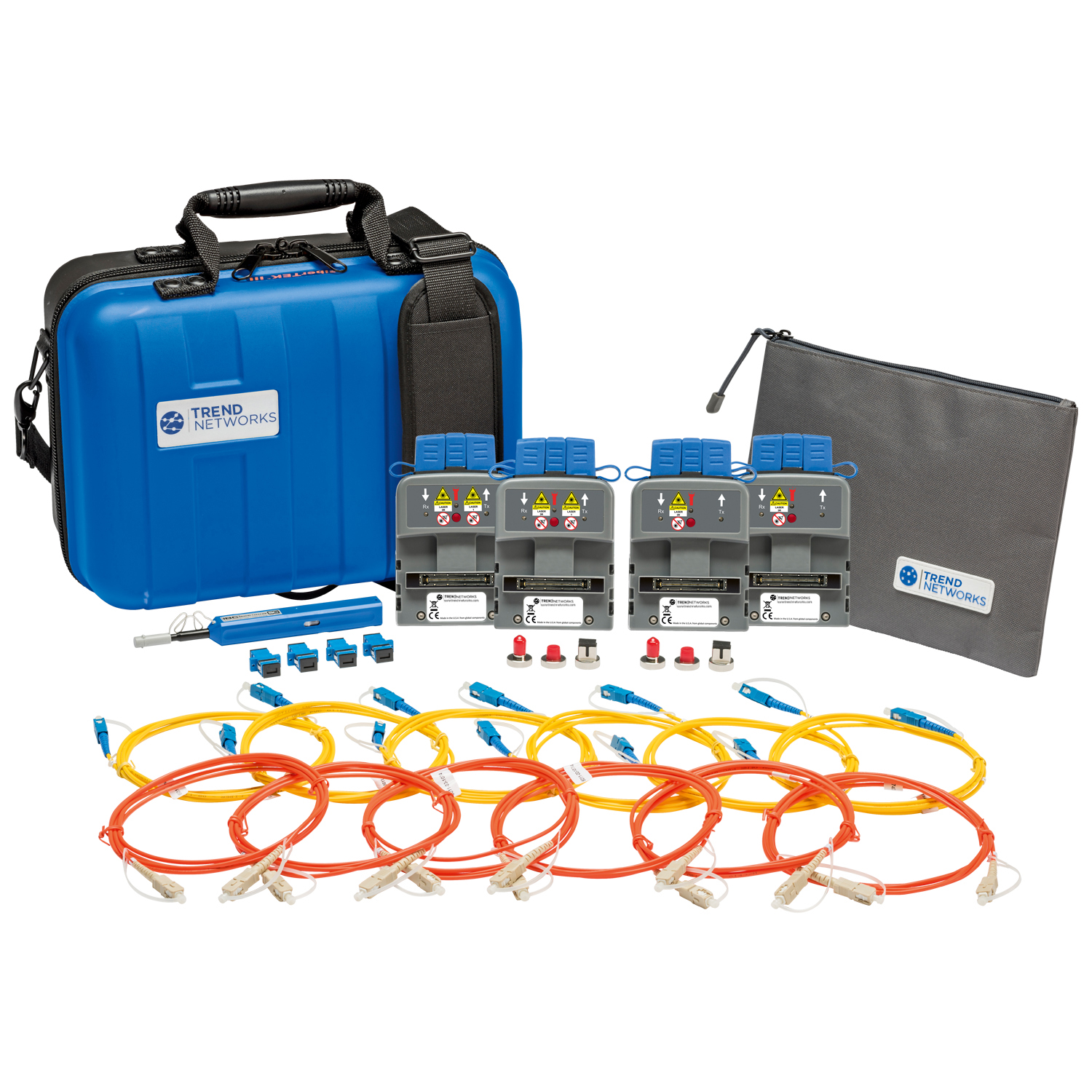
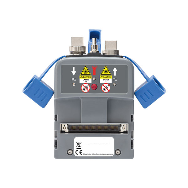
FiberTEK IV adapters turn your LanTEK IV / IV-S into a fibre certifier. For fast and simple certification of high bandwidth single-mode and multimode fibre optic cabling.
- Attenuation/insertion loss (dB) measurement
- Multimode and single-mode options
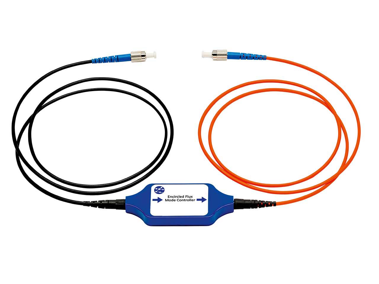
- Encircled Flux compliant (optional)
- Built-in visible light source for troubleshooting
- Full Tier 1 fibre certification
- Complies with TIA/ISO/IEC
POA
Overview
FIBERTEK IV – FIBRE CERTIFICATION ADAPTERS FOR THE LANTEK IV-S
FiberTEK IV adapters are used with LanTEK IV-S for fast and simple certification of high bandwidth single-mode and multimode fibre optic cabling including support for encircled flux testing (optional).
To pinpoint fibre cabling faults every FiberTEK IV adapter includes a built-in visible light source to help you visually pinpoint faults and locate fibre ports.
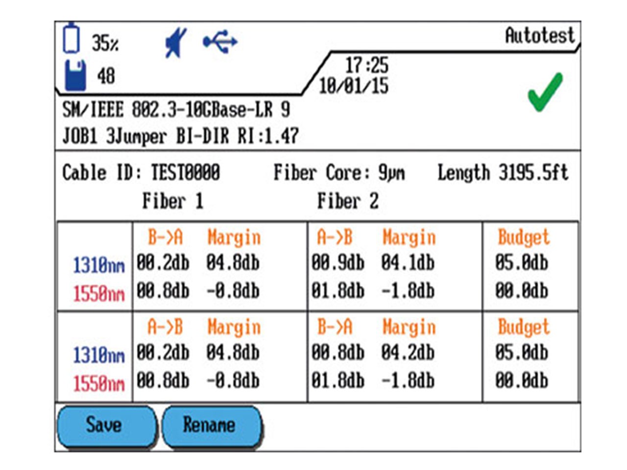
FiberTEK IV provides optical loss (dB) measurements meeting Tier 1 certification requirements.
Available in multi-mode (850/1300nm) and single mode (1310/1550nm) varieties.
Click here to view the LanTEK IV-S cable certifier.
Product features
Product models
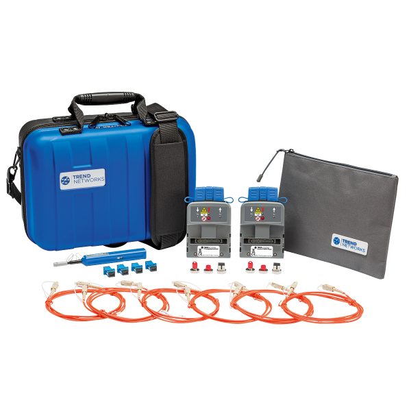
FIBERTEK IV-MM LED KIT
R164008 - FiberTEK® IV multimode (850/1300nm) kit with LED light sources for standard multimode fibre.
POA
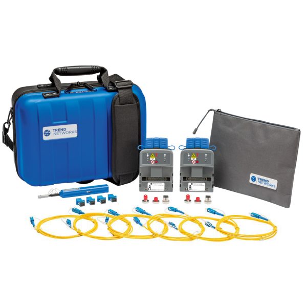
FIBERTEK IV-SM LASER KIT
R164009 - FiberTEK IV single mode (1310/1550nm) kit with laser light sources for single mode fibre.
POA
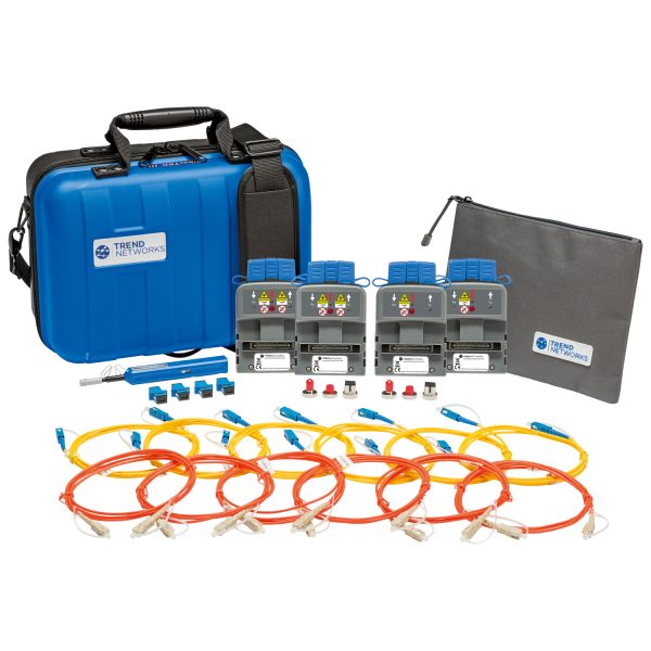
FIBERTEK IV-MM LED & SM LASER KIT
R164010 - FiberTEK IV combination MM/SM kit with LED MM sources and laser SM sources.
POA
Accessories

FT III/IV-Encircled Flux 50/125um Cable SC - SC
R164050 - FT III/IV-Encircled Flux 50/125um Cable SC - SC. Compatible with FiberTEK III and FiberTEK IV.
POA
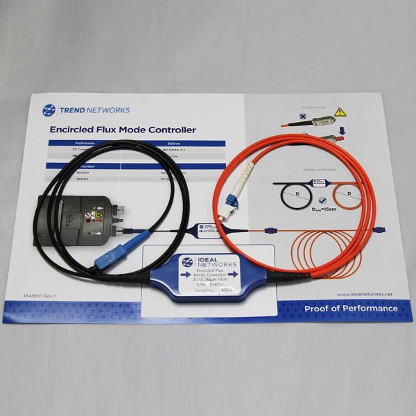
FT III/IV-Encircled Flux 50/125um Cable SC - LC
R164051 - FT IV-Encircled Flux 50/125um Cable SC - LC. Compatible with FiberTEK III and FiberTEK IV.
POA
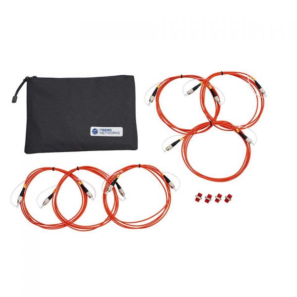
FT III-Cable Kit FC/PC MM 50/125um
R164054 - Description FT III-Cable Kit FC/PC MM 50/125um Kit contents 6 x 50/125um FC/PC - FC-PC Cable, 4 x FC/PC - FC/PC Coupler
POA
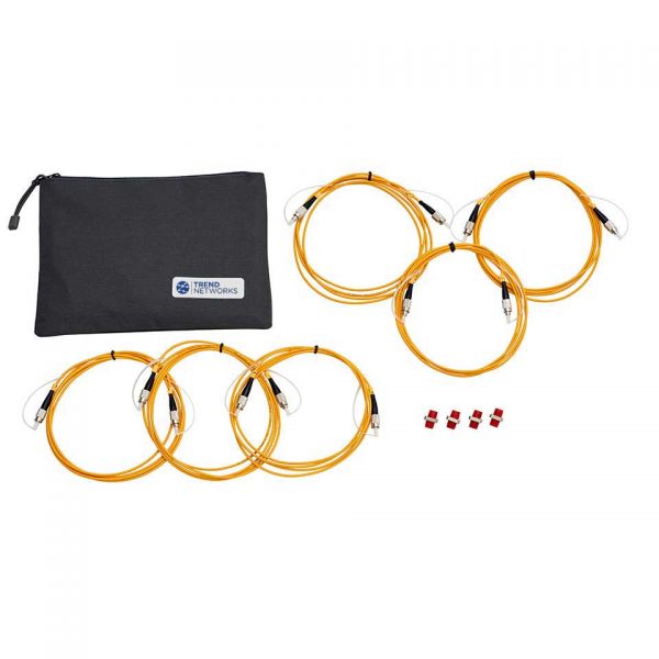
FT III-Cable Kit FC/PC SM 9/125um
R164058 - Description FT III-Cable Kit FC/PC SM 9/125um Kit contents 6 x 9/125um FC/PC - FC/PC Cable, 4 x FC/PC - FC/PC Coupler,
POA
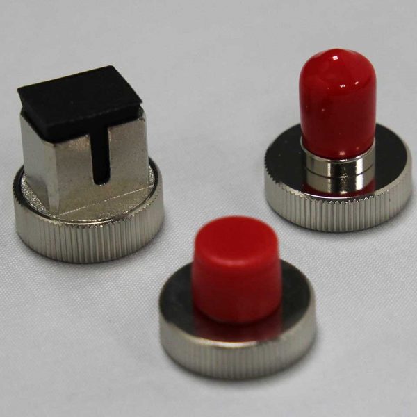
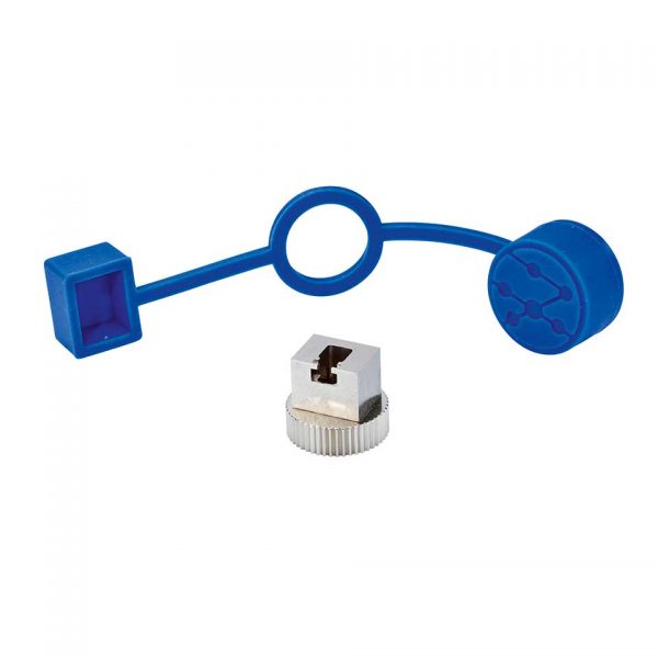
FT III/IV-Set of SC FC PC and ST Screw on Adaptors
R164060 - FT IV-Set of SC FC PC and ST Screw on Adaptors. Compatible with FiberTEK III and FiberTEK IV.
POA
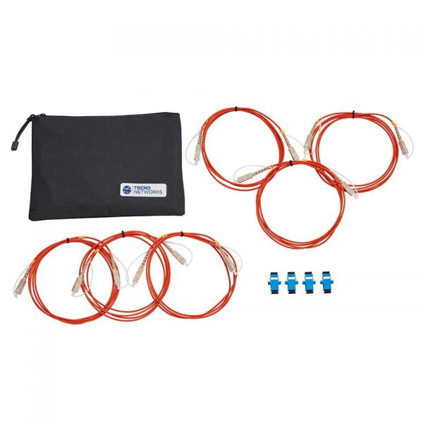
FT III-Cable Kit SC/PC MM 50/125um
R164053 - Description FT III-Cable Kit SC/PC MM 50/125um Kit contents 6 x 50/125um SC - SC Cable, 4 x SC - SC Coupler, 1 x Pouch
POA
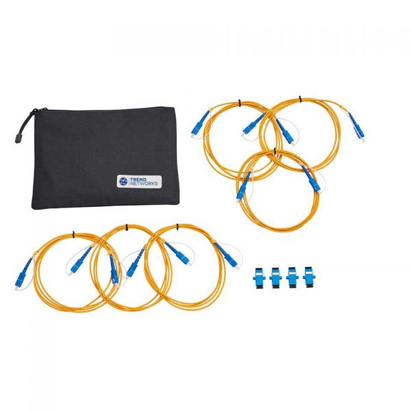
FT III-Cable Kit SC/PC SM 9/125um
R164057 - Description FT III-Cable Kit SC/PC SM 9/125um Kit contents 6 x 9/125um SC - SC Cable, 4 x SC - SC Coupler, 1 x Pouch
POA
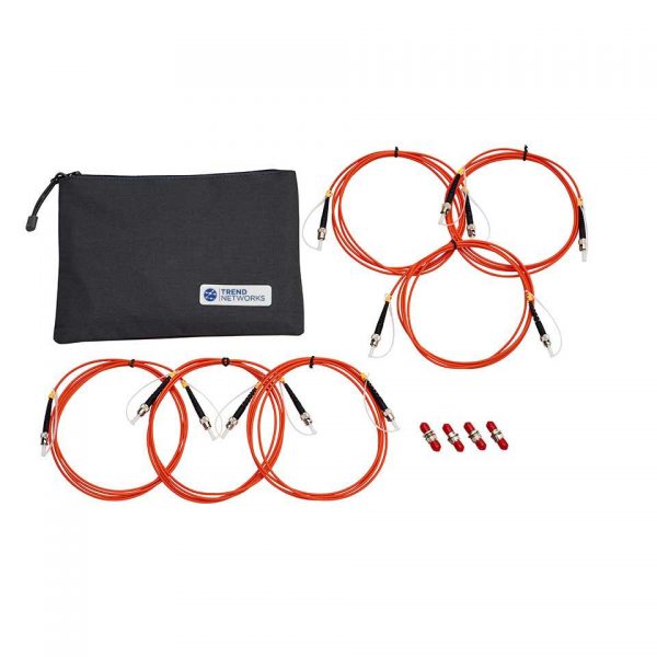
FT III-Cable Kit ST/PC MM 50/125um
R164055 - Description FT III-Cable Kit ST/PC MM 50/125um Kit contents 6 x 50/125um ST - ST Cable, 4 x ST - ST Coupler, 1 x Pouch
POA
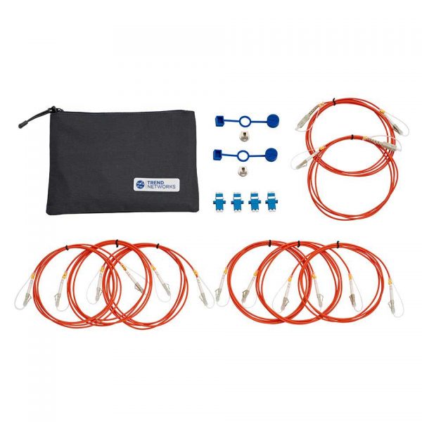
FT III-Cable and adapter kit LC MM 50/125µm
R164061 - Description FT III-Cable and adapter kit LC MM 50/125µm Kit contents 6 x 50/125um LC - LC Cable, 2 x 50/125um LC - SC
POA
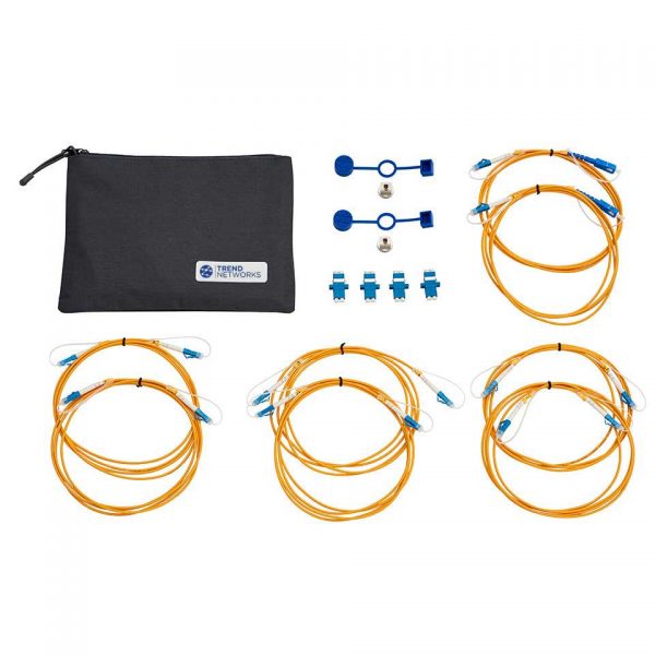
FT III-Cable and adapter kit LC SM 9/125µm
R164062 - Description FT III-Cable and adapter kit LC SM 9/125µm Kit contents 6 x 9/125um LC - LC Cable, 2 x 9/125um LC - SC Cab
POA
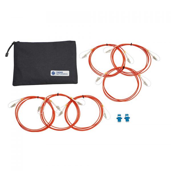
FT III-LC 50/125um F/Optic Cables and Couplers
R164056 - Description FT III-LC 50/125um F/Optic Cables and Couplers Kit contents 6 x 50/125um LC - LC Cable, 2 x LC - LC Coupler
POA
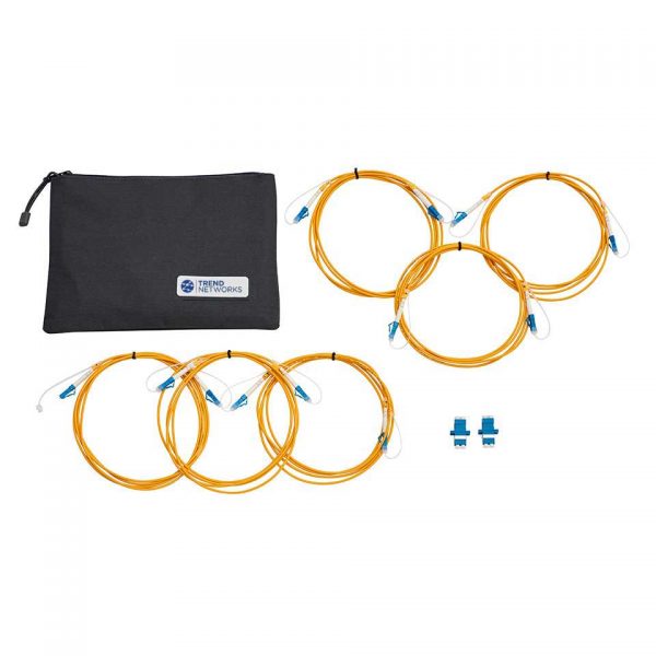
FT III-LC 9/125um F/Optic Cables and Couplers
R164059 - Description FT III-LC 9/125um F/Optic Cables and Couplers Kit contents 6 x 9/125um LC - LC Cable, 4 x LC - LC Double Co
POA

One-Click Fibre Cleaner STC-FC-1.25mm
33-963-11 - This 1.25mm One-click Cleaner is a high-performance and easy-to-use fibre tool that has been designed to clean both the
POA

One-Click Fibre Cleaner STC-FC2.5mm
33-963-10 - This 2.5mm One-click Cleaner is a high-performance and easy-to-use fibre tool that has been designed to clean both the m
POA
Videos

Manuals, Brochures
Download and view the latest manuals, quick reference guides, firmware and software updates, and approvals. Registration is required.
Frequently Asked Questions
- Q: What is the difference between single-mode and multimode fibre?A: Multimode fibre has a larger light carrying core of 50 or 62.5 microns compared to 9 microns for single-mode fibre. The larger core of multimode fibre captures more light than single-mode fibre allowing the use of low power LED light sources. The maximum bandwidth of multimode fibre is inversely proportional to length, i.e., doubling the length of a multimode cable reduces it’s bandwidth capacity by half. Multimode fibre is typically limited to lengths of 2,000 meters (6,560 ft). Single-mode fibre requires the use of higher power and more costly laser light sources but does not sacrifice bandwidth for distance. Single-mode fiber can be used at lengths of up to 40,000 meters (131,200 ft) while supporting 10 Gb/s data rates.
- Q: Which LanTEK IV models support FiberTEK IV?A: Both LanTEK IV-S 500 and LanTEK IV-S 3000 support FiberTEK IV.
- Q: Will LanTEK II or LanTEK III support FiberTEK IVA: No
- Q: Can I measure MPO connectors with FiberTEK IVA: Not directly. Due to the still not very high repeatability when disconnecting and connecting MPO connectors, TREND still recommends to use so called fan-out cables from MPO to SC or LC
- Q: Can I measure LC links with FiberTEK IVA: Yes, there are optional adapters available
- Q: Which products from Trend Networks test Tier-1 / Tier-2 ?A: The FiberTEK IV tests Tier-1. The OTDR II tests Tier-2.
- Q: Do you need to do both Tier 1 (OLTS testing) and Tier 2 (OTDR testing) to complete a Tier 2 certification?A: Tier-2 certification is a supplement to Tier-1 certification meaning both an attenuation measurement with a power meter/light source (OLTS) and an OTDR measurement are required. It is for this reason many OTDRs have options for an integrated power meter. With the power meter built in to the OTDR, both measurements can be stored on a single instrument to simply reporting.
- Q: When testing 2 fibres with an OLTS, can the fibres be looped at the far end so one person can test both fibres with a single tester or does each fibre need to me measured individually?A: Looping the fibre is not a recognised method of OLTS testing because if the loss is too high you cannot know which fibre has a problem. When someone has an OTDR w/power meter the assumption is a stand-alone light source will be used at the opposite end of the cable to test each fibre individually. Having the OTDR w/ power meter is more convenient because the results for both Tier 1 and 2 tests can be stored on the same piece of test equipment.
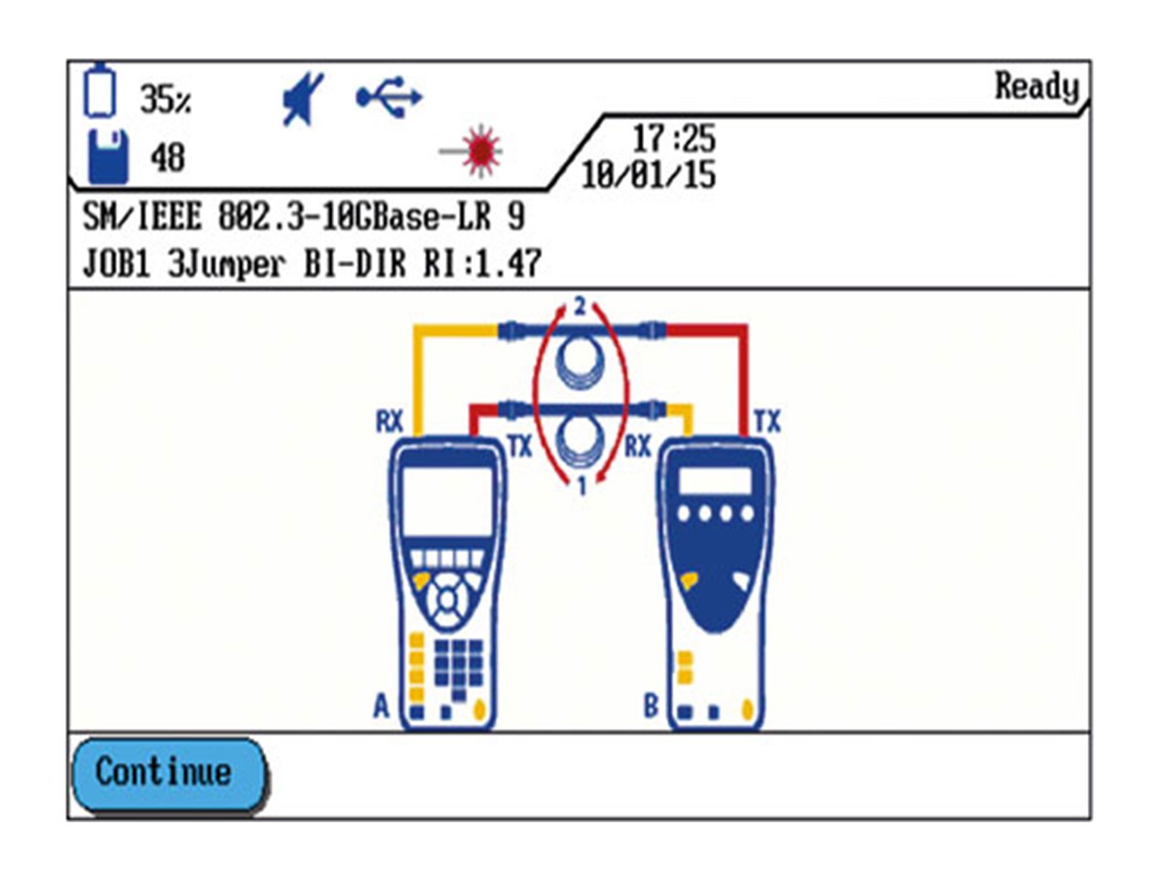
- Q: Is bi-directional testing required for OLTS & OTDR testing ?A: Standards do not require bi-directional testing.For multimode fibre they require testing at 1 wavelength. 2 wavelength testing is optional.For single-mode fibre 2 wavelength testing is highly recommended for two reasons: First – single-mode cables can be long enough that the total attenuation can be very different at each wavelength because attenuation from bends in the cable depend on the wavelength. Second and more importantly - 2 wavelength testing can identify a bend vs a splice. Attenuation for a bend is different depending on the wavelength, but attenuation from a splice should be very similar at both wavelengths. The OTDR software assumes an event with similar loss at both wavelengths is a splice and an event with different loss values is a bend. This is the only way it can correctly identify a splice vs a bend. Bi-directional testing is useful for identifying mismatched fibre types. The loss with an OLTS or OTDR should be the same in each direction. However, if different types of fibre are connected together such as 50 & 62.5um multimode or single-mode fibre with different NA values (numerical aperture) the loss will be different in one direction vs the other. With an OLTS you see only the total loss, but a difference in measurements indicates there is a mismatch of sorts. An OTDR will show the location of the mismatch. A splice measured in one direction may show +0.5dB (gain) and in the other direction may show -0.3dB. When added together the result is -0.2dB which is the actual value of the splice. Standards do not require bi-directional testing. It is purely optional and used to identify issues like those mentioned above.
- Q: Does Tier-1 testing require polarity and length measurements ?A: There is no requirement to identify the polarity of the fibres, but this is a good reason for bi-directional testing. If the fibres are tested in both directions polarity does not matter. The cables are supposed to be installed so that the TX/RX is reversed but this is a documentation issue more than testing. The requirement to measure length depends on the standard being tested. TIA/ISO limit the length for horizontal fibre runs to 90m just like copper cable, so it is required to test length. TIA/ISO also have specifications for cable attenuation per km. For example multimode 850 must be 3.5dB/km or less - this is for the fibre only, not including connectors. Obviously to perform the calculation the cable length must be measured. This is difficult with an OLTS because it does not know how many connectors are in the link and are affecting the total loss. Practically speaking, an OTDR is the only way to do this measurement accurately. Some application standards like IEEE 10GBase-SX (10Gbps @ 850nm) only have a specification for maximum loss, not length. So as long as the loss is under the limit, cable length does not matter. There are big differences when testing TIA/ISO vs IEEE. TIA/ISO standards are written without reference to a specific application and are intended to provide installation guidelines for a generic cabling system that supports many different applications. IEEE test limits apply to each application and allow a user to ensure that a specific application will run on the cabling being tested. Cabling installers rarely know what application the network owners plan to use which is why installers test to TIA/ISO generic cabling standards. Most IEEE standards specify minimum cable distances for multimode fibre for the different grades: OM2, OM3, OM4 and OM5. This only means the bandwidth specified by the fibre grade is available to at least the minimum distance. It is not a distance limit and the bandwidth may be available at further distances for fibre that exceeds the minimum bandwidth ratings.

 Free Shipping