
OTDR II TESTER
R230000
- Tablet-inspired design
- 7-inch, outdoor-enhanced touchscreen
- Dynamic range of up to 36 dB in SM and 29 dB in MM
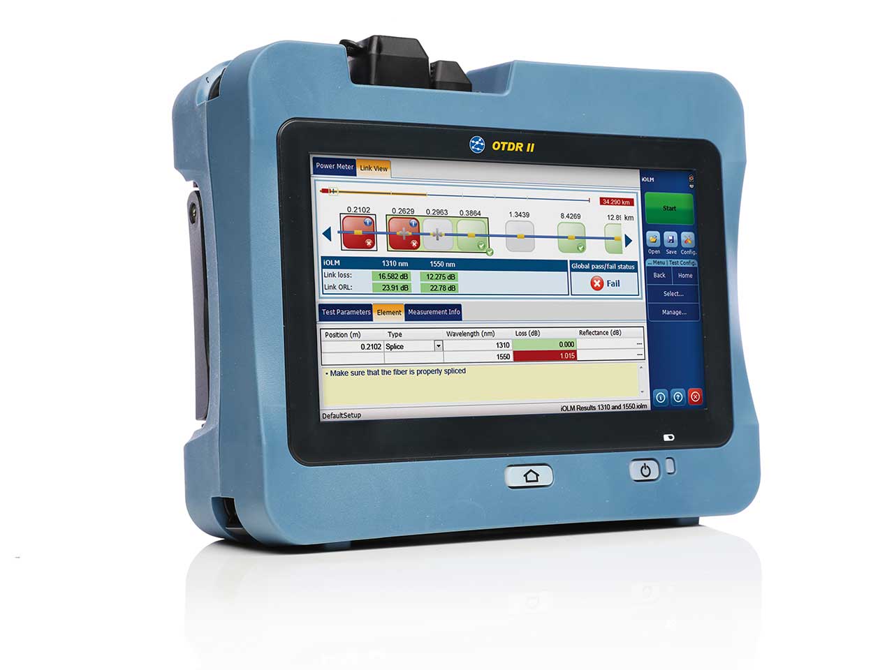
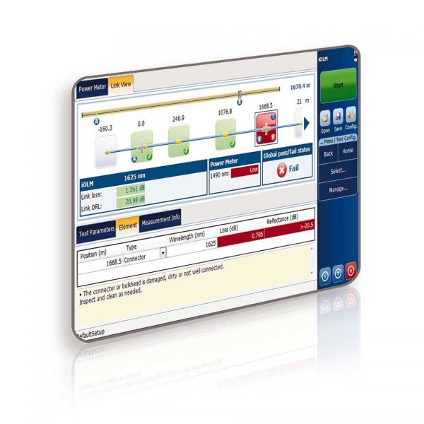
- iOLM: Turns complicated graphs into easy to read diagrams
- Pass/fail status for each event
$13,000 MSRP
 Free Shipping
 Overview
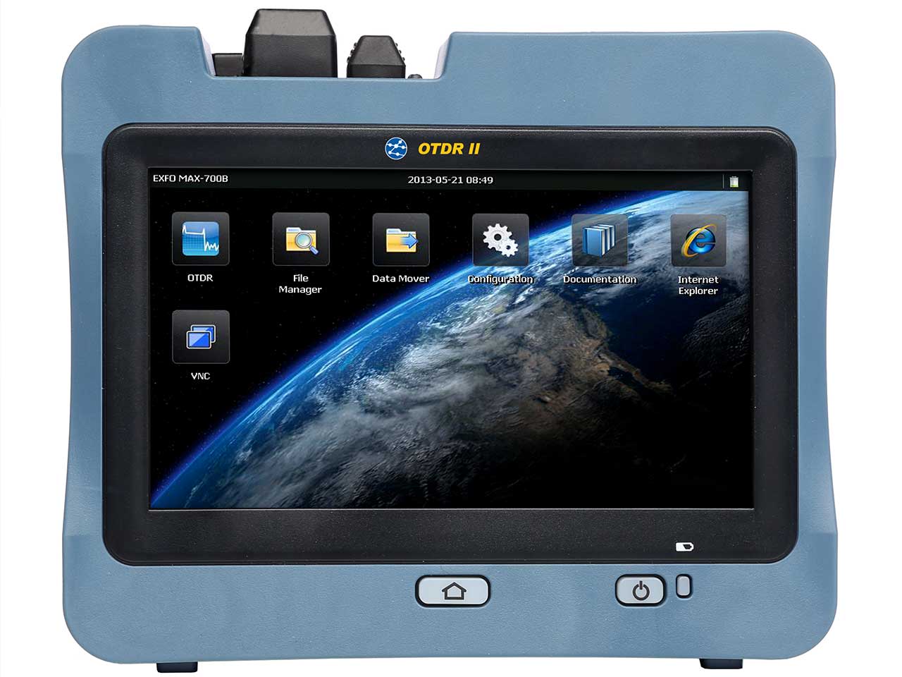
The OTDR II is the first tablet inspired OTDR that is handy, lightweight and rugged enough for any environment.
With a 7-inch outdoor enhanced touchscreen, the most efficient hand held display in the industry, it delivers an unprecedented user experience. Its intuitive user interface including onboard manual ensures a fast learning curve. Plus, its new and improved OTDR platform offers icon-based functions, instant boot-up, automatic macrobend finders as well as improved auto and real-time modes
Product features
Key features:
- iOLM (Intelligent Optical Link Mapper) – automatic configuration and multiple measurements on the same link provides the best possible measurements regardless of fiber configuration
- Onboard PDF reporting
- Macro bend detection
- Short attenuation dead zone: MM: 2.5 m/SM: 3 m and event dead zone: MM: 0.5 m/SM: 0.7 m for accurate location and characterization of events
- Quad wavelength (850/1300/1310/1550) for both multimode and single-mode testing
- Each fiber may be tested at two wavelengths in a single Autotest
- Provides results in only a few seconds
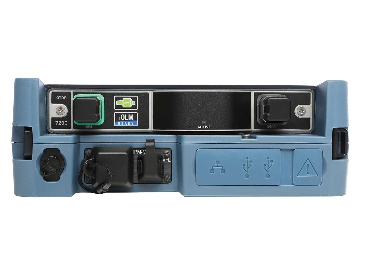
- Interchangeable fiber adapters with a wide variety of available configurations
- Transfer test results to PC via USB flash drives or USB cable
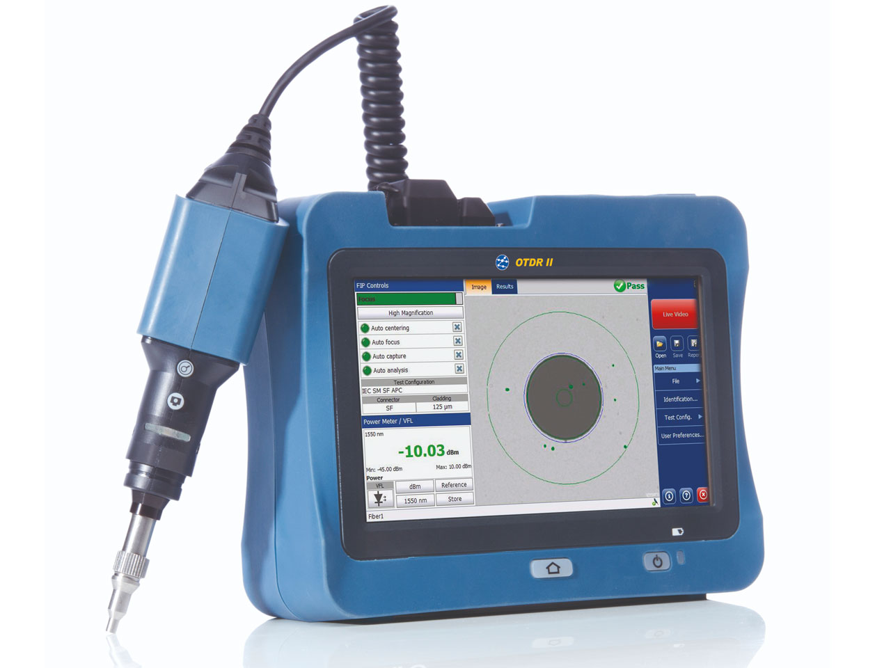
- Optional video inspection micro scope to check connectors for cleanliness or damage
- Provides simple PASS/FAIL results and macro bend detection in single-mode fibers that helps users identify bends or kinks in the cable, saving time during installation and troubleshooting
- Small size for one handed operation
- Rubber over-mold for enhanced drop protection
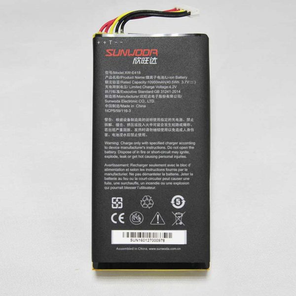
- 1 lithium-ion battery provides up to 12 hours operation
- Warranty is one year and we recommend an annual calibration
- Rugged carrying case for field use
The handheld OTDR… reinvented.
The OTDR II is finally bringing the iOLM, an intelligent OTDR-based application, to the handheld market. This advanced software turns even the most complex trace analysis into a simple, one-touch task. The iOLM feature removes the need for analysis of complicated OTDR traces.
However, the traces are available on the reports and PC software if required. For traditional OTDR users an OTDR II trace option is available to view and analyze traces on the tester.
The amazing 12-hour battery life will never let a technician down, and the plug-and-play hardware options, like the power meter and the USB video probe, make every technician’s job easier. Unlike traditional OTDR’s, OTDR II does not require specific launch cords which makes testing more cost effective and user-friendly.

The entry-level solution designed for all your testing needs
The OTDR II/iOLM features a dynamic range of 36 dB in single-mode and 29 dB in multimode, as well as industry-leading dead zones. This ensures efficient testing of closely spaced events such as patchcords in data centers, or patch panels in central offices (COs). The OTDR II is optimized for point-to-point testing of any access network, and is suitable for testing through 1×32 splitters.
Get the best out of your data post-processing
The FastReporter3 basic software included as standard allows users to create typical results of single measurements. The optional full license FastReporter3 is the perfect complement to your OTDR II, and can be used to combine multiple test results of the OTDR II and fiber probe into detailed PDF documentation.
Designed for off-line analysis, FastReporter3 offers reliable data and report management in a user-friendly environment. A 30-day trial version of the full license FastReporter3 is included.

Alternatively you can use the onboard reporting tool to create comprehensive PDF documentation.
For further details of the difference between the FastReporter3 basic software and the full license of FastReporter3 software, please see chart below.
iOLM – removing the complexity from OTDR testing

In response to these challenges, TREND Networks are providing a better way to test fiber optics:
The intelligent Optical Link Mapper (iOLM) turns complicated graphs into an easy to read diagram displaying all events along the link with pass/fail status for each event. The iOLM is an OTDR-based application designed to simplify OTDR testing by eliminating the need to configure parameters, and/or analyze and interpret multiple complex OTDR traces. Its advanced algorithms dynamically define the testing parameters, as well as the number of acquisitions that best fit the network under test. By correlating multi-pulse widths on multiple wavelengths, the iOLM locates and identifies faults with maximum resolution – all at the push of a single button.

Visual Fault Locator (VFL)
The plug-and-play VFL easily identifies breaks, bends, faulty connectors and splices, in addition to other causes of signal loss. This basic, yet essential troubleshooting tool should be part of every field technician’s toolbox and comes with the standard unit. The VFL visually locates and detects faults over distances of up to 5 km by creating a bright red glow at the exact location of the fault on single-mode or multimode fibers.
Optical Power Meter and VFL option
A high-level power meter (GeX) that can measure up to 27 dBm, the highest in the industry. This is essential for hybrid fiber-coaxial (HFC) networks or high-power signals. If used with an auto-lambda/auto-switching compatible light source, the power meter automatically synchronizes on the same wavelength, thus avoiding any risk of mismatched measurement.
Installation is quick and easy, and can be performed by the user without the need for any software update. Simply exchange the VFL board with the new optical power meter and VFL board.
- Seven standard calibrated wavelengths
Fiber connector inspection and certification
– the essential first step before any OTDR testing
Taking the time to properly inspect a fiber optic connector using an TREND Networks fiber inspection probe can prevent a host of issues from arising further down the line, thus saving you time, money and trouble.

Did you know that the connector of your OTDR II/iOLM is also critical?
The presence of a dirty connector at an OTDR port or launch cable can negatively impact your test results, and even cause permanent damage during mating. Therefore, it is critical to regularly inspect these connectors to ensure that they are free of any contamination. Making inspection the first step of your OTDR best practices will maximize the performances of your OTDR and your efficiency.
FastReporter3 Software Comparison Chart between basic version (comes as standard) and optional full software license (30-day trial):

Applications –
- Tier-2 certification of fiber optic networks that require specific testing to ISO/IEC and TIA international standards
- Troubleshooting and fault finding of fiber optic links
- Access network construction and troubleshooting
- Central-office (CO) link certification
- Data center and enterprise networks
- LAN/WAN characterization
Accessories
Fast Reporter Software for OTDR II
R230077 - Fast Reporter 3 Software for OTDR II. Delivered as a USB dongle with 2 GB Flash Memory. FastReporter has a highly intuit
$1,275 MSRP

VFL and power meter option for OTDR II
R230050 - VFL and power meter option for OTDR II
$1,145 MSRP

Power Supply, will ship with US, UK and EU cords for OTDR II
R230053 - Power supply (US/UK/EU cords) for OTDR II
$85 MSRP
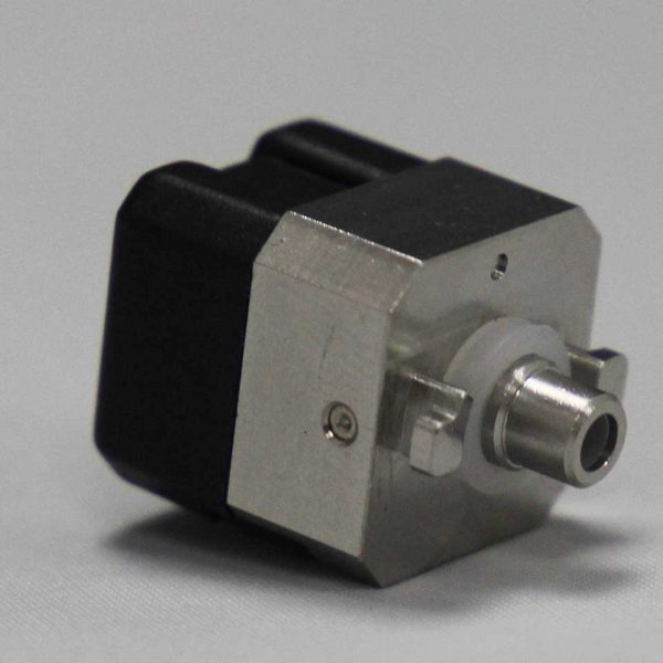
FC adapter for OTDR II and OC I
R230054 - FC adapter for OTDR II and OC I
$130 MSRP
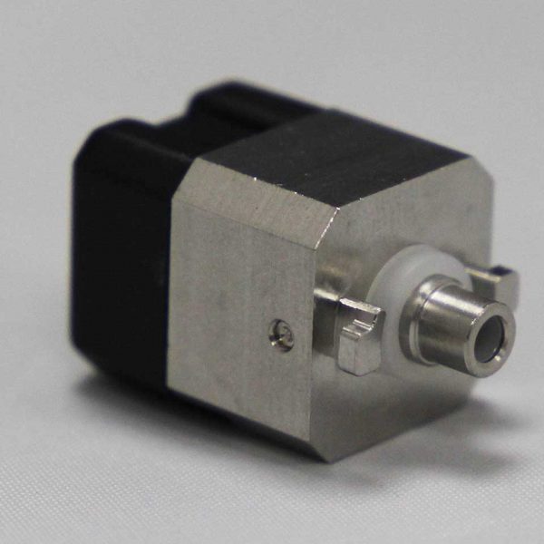
ST adapter for OTDR II and OC I
R230055 - ST adapter for OTDR II and OC I
$130 MSRP
SC adapter for OTDR II and OC I
R230056 - SC adapter for OTDR II and OC I
$130 MSRP
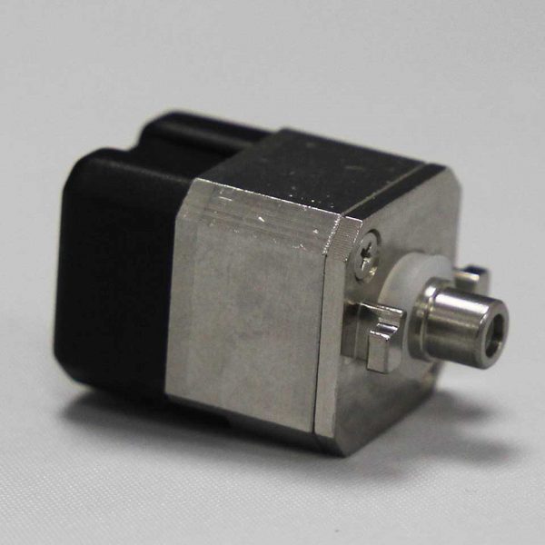
LC adapter for OTDR II and OC I
R230057 - LC adapter for OTDR II and OC I
$200 MSRP
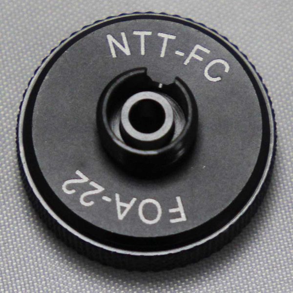
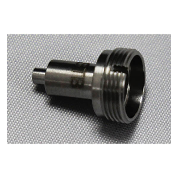
FC and NEC-d3 adapter for OTDR II Power Meter Option
R230058 - FC and NEC-d3 adapter for OTDR II power meter option
$95 MSRP
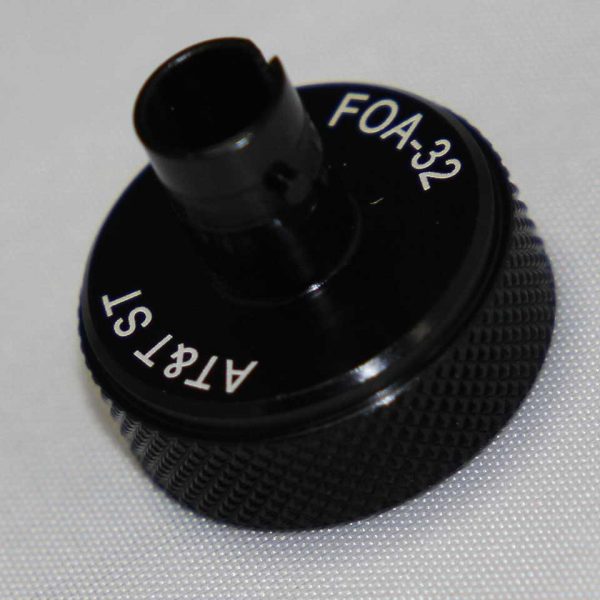
ST adapter for OTDR II Power Meter Option
R230059 - ST adapter for OTDR II power meter option
$95 MSRP

SC adapter for OTDR II Power Meter Option
R230060 - SC adapter for OTDR II power meter option
$95 MSRP
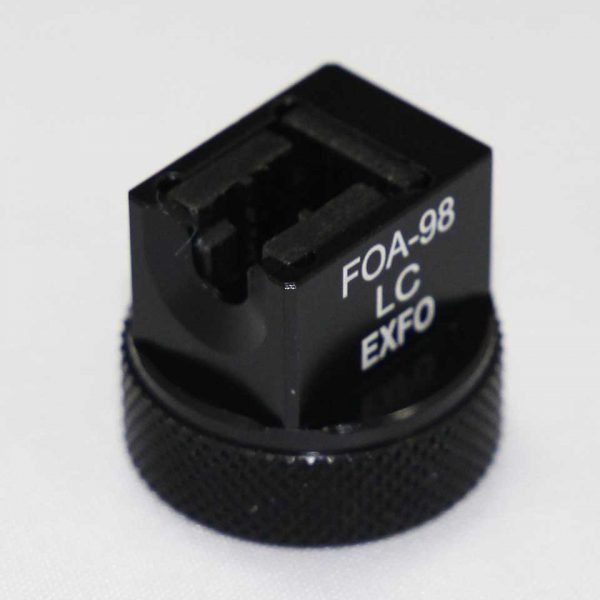
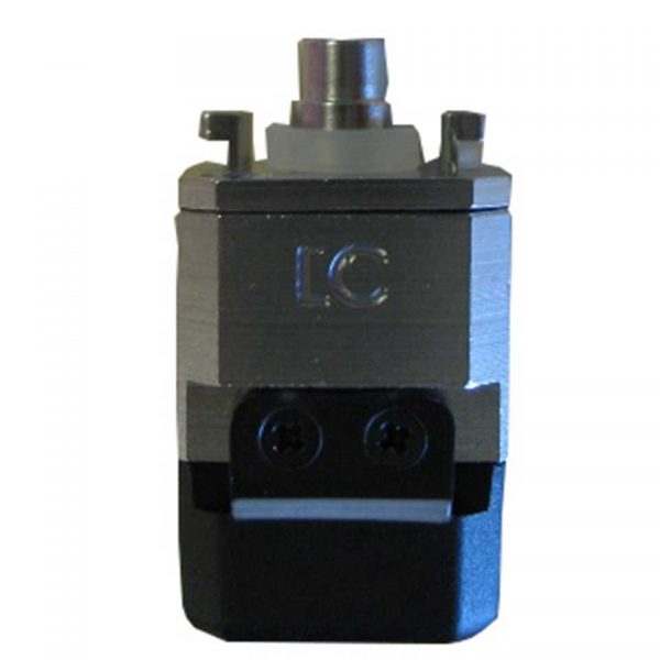
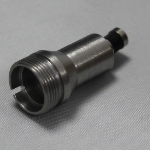
LC adapter for OTDR II Power Meter Option
R230061 - LC adapter for OTDR II power meter option
$180 MSRP
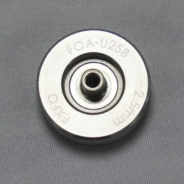
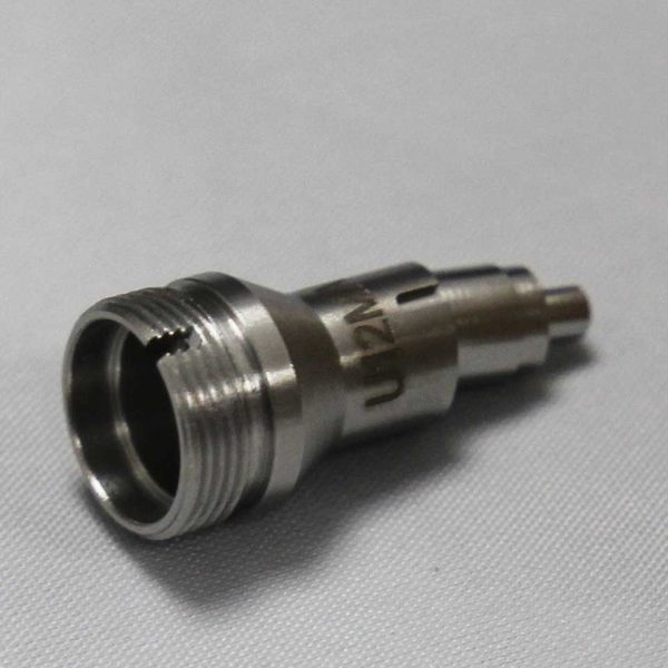
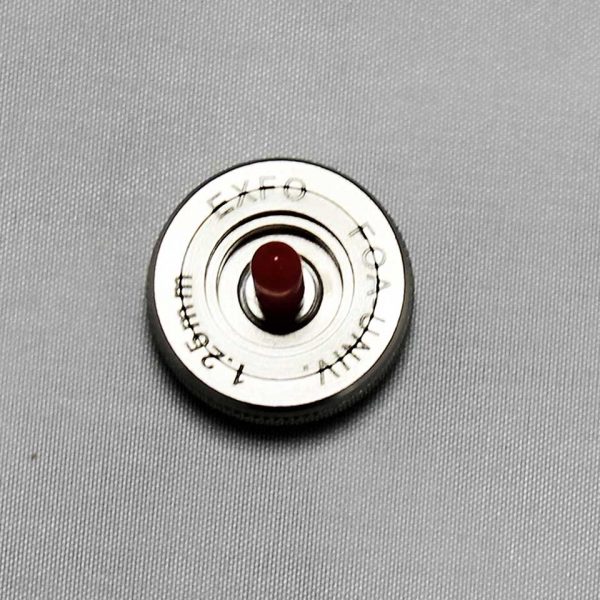
Universal 2.5mm adapter for OTDR II Power Meter Option
R230063 - Universal 2.5 mm adapter for OTDR II power meter option
$190 MSRP
SC/APC Tip for Bulkhead Adapter for Fibre Inspection Probe (R230002)
R230064 - SC/APC tip for bulkhead adapter for fibre inspection probe (R230002)
$180 MSRP
ST Tip for Bulkhead Adapter for Fibre Inspection Probe (R230002)
R230065 - ST tip for bulkhead adapter for fibre inspection probe (R230002)
$95 MSRP
Universal Patchcord Tip for 1.25 mm Ferrules for Fibre Inspection Probe (R230002)
R230066 - Universal patchcord tip for 1.25 mm ferrules for fibre inspection probe (R230002)
$95 MSRP
Universal Patchcord Tip for 1.25 mm/APC Ferrule for Fibre Inspection Probe (R230002)
R230067 - Universal patchcord tip for 1.25 mm/APC ferrule for fibre inspection probe (R230002)
$150 MSRP
Universal Patchcord Tip for 2.5 mm Ferrule for Fibre Inspection Probe (R230002)
R230068 - Universal Patchcord tip for 2.5 mm ferrule for fibre inspection probe (R230002)
$95 MSRP
Universal Patchcord Tip for 2.5 mm/APC Ferrule for Fibre Inspection Probe (R230002)
R230069 - Universal Patchcord tip for 2.5mm/APC ferrule
$150 MSRP
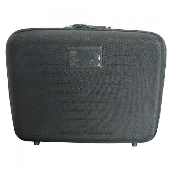
Semi rigid carrying case for OTDR II and OC I
R230074 - Semi rigid carrying case for OTDR II and OC I
$170 MSRP
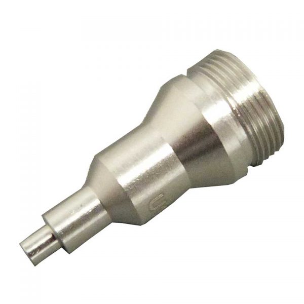
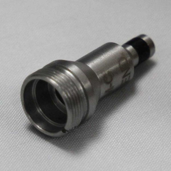
Universal 1.25mm adapter for OTDR II Power Meter Option
R230062 - Universal 1.25 mm adapter for OTDR II power meter option
$190 MSRP
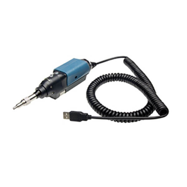
Video Inspection Probe
R230002 - Video inspection probe with universal adapter
$2,785 MSRP

One-Click Fiber Cleaner STC-FC-1.25mm
33-963-11 - This 1.25mm One-click Cleaner is a high-performance and easy-to-use fiber tool that has been designed to clean both the
$90 MSRP

One-Click Fiber Cleaner STC-FC2.5mm
33-963-10 - This 2.5mm One-click Cleaner is a high-performance and easy-to-use fiber tool that has been designed to clean both the m
$90 MSRP

Software, Brochures
Download and view the latest manuals, quick reference guides, firmware and software updates, and approvals. Registration is required.
Frequently Asked Questions
- Q: What is iOLM?A: The intelligent Optical Link Mapper translates an difficult to read OTDR plot into a very easy to understand map of the link under test
- Q: Why do I need a high spec OTDR if I only want to test short links like they appear in a backbone or data center?A: The challenge is that connectors and other events like splices typically are very close to each other - especially when it comes to short links. In order to be able to see and pass/fail all events properly, you need an OTDR with excellent performance in dead zones as well as a high dynamic range. The OTDR II can accurately detect events that are 0.8m away from each other
- Q: But… Your OTDR is quite expensive?A: True, it is not the cheapest tester on the market. There are devices on the market that claim to be an OTDR which are by far cheaper then our device. However, those devices do not have not the measurement capabilities to measure in LAN / Campus environments. The challenge in LAN / campus is the combination of very short links with a high number of connectors and splices. Lower grade OTDRs do not have the necessary short pulse width to show enough resolution and give enough accuracy to “see” all events individually
- Q: But.. Your OTDR is no real OTDR since it does not offer plots?A: The OTDR II is indeed a highly accurate OTDR. iOLM (intelegent optical link mapper) takes OTDRs to a completely new level of OTDR measurements since it completely removes the usual guess work to try and interpret an OTDR plot. The iOLM gives accurate results for all events within a fibre optic link. If you still want to see the classical OTDR plot, the plots are available in the printed reports of the device, in the PC software or in the OTDR II trace option SOFT230OTDR
- Q: Which products from TREND Networks Tier-1 / Tier-2 ?A: The OC I and FiberTEK III test Tier-1. The OTDR II tests Tier-2.
- Q: Do you need to do both Tier 1 (OLTS testing) and Tier 2 (OTDR testing) to complete a Tier 2 certification ?A: Tier-2 certification is a supplement to Tier-1 certification meaning both an attenuation measurement with a power meter/light source (OLTS) and an OTDR measurement are required. It is for this reason many OTDRs have options for an integrated power meter. With the power meter built in to the OTDR, both measurements can be stored on a single instrument to simply reporting.
- Q: When testing 2 fibers with an OLTS, can the fibers be looped at the far end so one person can test both fibers with a single tester or does each fiber need to me measured individually?A: Looping the fiber is not a recognized method of OLTS testing because if the loss is too high you cannot know which fiber has a problem. When someone has an OTDR w/power meter the assumption is a stand-alone light source will be used at the opposite end of the cable to test each fiber individually. Having the OTDR w/power meter is more convenient because the results for both Tier 1 and 2 tests can be stored on the same piece of test equipment.
- Q: Is bi-directional testing required for OLTS & OTDR testing ?A: Standards do not require bi-directional testing. For multimode fiber they require testing at 1 wavelength. 2 wavelength testing is optional. For single-mode fiber 2 wavelength testing is highly recommended for two reasons: First – single-mode cables can be long enough that the total attenuation can be very different at each wavelength because attenuation from bends in the cable depend on the wavelength. Second and more importantly - 2 wavelength testing can identify a bend vs a splice. Attenuation for a bend is different depending on the wavelength, but attenuation from a splice should be very similar at both wavelengths. The OTDR software assumes an event with similar loss at both wavelengths is a splice and an event with different loss values is a bend. This is the only way it can correctly identify a splice vs a bend. Bi-directional testing is useful for identifying mismatched fiber types. The loss with an OLTS or OTDR should be the same in each direction. However, if different types of fiber are connected together such as 50 & 62.5um multimode or single-mode fiber with different NA values (numerical aperture) the loss will be different in one direction vs the other. With an OLTS you see only the total loss, but a difference in measurements indicates there is a mismatch of sorts. An OTDR will show the location of the mismatch. A splice measured in one direction may show +0.5dB (gain) and in the other direction may show -0.3dB. When added together the result is -0.2dB which is the actual value of the splice. Standards do not require bi-directional testing. It is purely optional and used to identify issues like those mentioned above.
- Q: Does Tier-1 testing require polarity and length measurements ?A: There is no requirement to identify the polarity of the fibers, but this is a good reason for bi-directional testing. If the fibers are tested in both directions polarity does not matter. The cables are supposed to be installed so that the TX/RX is reversed but this is a documentation issue more than testing. The requirement to measure length depends on the standard being tested. TIA/ISO limit the length for horizontal fiber runs to 90m just like copper cable, so it is required to test length. TIA/ISO also have specifications for cable attenuation per km. For example multimode 850 must be 3.5dB/km or less - this is for the fiber only, not including connectors. Obviously to perform the calculation the cable length must be measured. This is difficult with an OLTS because it does not know how many connectors are in the link and are affecting the total loss. Practically speaking, an OTDR is the only way to do this measurement accurately. Some application standards like IEEE 10GBase-SX (10Gbps @ 850nm) only have a specification for maximum loss, not length. So as long as the loss is under the limit, cable length does not matter. There are big differences when testing TIA/ISO vs IEEE. TIA/ISO standards are written without reference to a specific application and are intended to provide installation guidelines for a generic cabling system that supports many different applications. IEEE test limits apply to each application and allow a user to ensure that a specific application will run on the cabling being tested. Cabling installers rarely know what application the network owners plan to use which is why installers test to TIA/ISO generic cabling standards. Most IEEE standards specify minimum cable distances for multimode fiber for the different grades: OM2, OM3, OM4 and OM5. This only means the bandwidth specified by the fiber grade is available to at least the minimum distance. It is not a distance limit and the bandwidth may be available at further distances for fiber that exceeds the minimum bandwidth ratings.
- Q: What is the warranty for the OTDR II ?A: The warranty is 1 year.
- Q: Does the OTDR II require calibration ?A: We recommend an annual calibration.
Latest articles

OUR PROMISE
Lifetime Support Promise – we’ll calibrate and repair the testing equipment you buy from us for as long as you use it.*
Depend On Our Data – TREND AnyWARE Cloud is the only system for certification, network and bandwidth testing.
Rapid Service – If we can’t answer your Technical Support call instantly we strive to return the call within 2 business hours.*
