Differences Between Transmission Testing and Qualification Testing
Three types of testers are available to installers of local area network (LAN) cabling who require testing beyond what a verifier (wiremapper) provides: qualifiers, transmission testers, and cable certifiers. At the top end, cable certification testers perform comprehensive, high-frequency measurements of the electrical characteristics of a cabling system to ensure it meets the requirements of the TIA-568 and ISO 11801 standards. Up until the mid-2000s, certifiers and verifiers were the only options installers had for testing LAN cabling.
In about 2004, a new type of tester offered cable installers an option to document an installation when a certifier was not needed to provide test reports for a warranty program. The TIA and ISO cabling standards define the measurements, pass/fail limits and accuracy requirements for certifiers to test various performance cabling categories, such as Category 5, 5e and 6 (called “classes” in ISO standards). These new testers did not have defined parameters in the standards for commercial building cabling systems the way that certifiers did. The word “qualification” first appeared in a standard when the TIA-570-B-a standard for residential cabling-was published. The section of the 570-B standard that addresses cabling is vague compared to the content of the 568 series of standards.
TIA-570-B reads: “Cable qualification tests the cabling to determine that certain network technologies (e.g. 1000Base-T, 100Base-T, FireWire) will perform on the cabling system. Cable qualification shall be performed using network equipment installed on the cabling, or by use of a qualification test instrument.”
There are no further definitions of qualification. This broad statement opened the door for new types of testers that have capabilities exceeding those of a verifier and do not meet the requirement of a certifier. The rest is left up to the manufacturer to decide how their product will “qualify” a cable. The result is that different qualifiers can be purchased that do not measure or report the same parameters and can give completely different results on the same cabling link.
Qualifiers and Transmission Testers
A standard provides a set of rules allowing different companies to manufacture products that operate with each other or provide the same function. Different brands of certifiers that meet the TIA/ISO standards will report the same results on a cabling link when compared side-by-side. Unless a qualifier is testing to a standard, there is no way for the user to compare the measurement results of one tester to another. The reason this alternate, yet undefined method of testing is in TIA-570-B is to encourage performance testing of residential cabling to support high-bandwidth applications without requiring a residential installer to purchase an expensive certifier that meets the TIA-568/ISO-11801 requirements.
As an alternative, some companies introduced a technology that is commonplace in wide area network (WAN) testing. Data transmission testing, or simply transmission testing, is a tried-and-true method of testing that has the advantage of pass/fail parameters defined by a standard, meaning the tester is not providing a “trust-me” report. A “trust-me” report is one in which the measurements, measurement criteria and pass/fail limits are either unspecified or cannot be traced back to an industry-recognized test method.
Within the scope of LAN testing, a transmission tester fits into the category of a qualification tester because it is providing performance testing of the cabling but is not performing the same measurements of a certifier. However, to call a transmission tester a qualifier is an understatement. Unlike LAN cable qualifiers, transmission testers perform specific measurements and make pass/fail determinations in accordance with an industry standard. The standard used for LAN testers is the IEEE 802.3 Ethernet standard that is an umbrella document for all the different varieties and implementations of Ethernet.
The Gigabit Ethernet standard, IEEE 802.3ab, defines the data rate, frame size, and allowable delay and loss rate for a “good” Ethernet system. By referencing the 802.3ab standard, a transmission tester provides results that the user can be assured represent the true capabilities of the cabling and not what the tester manufacturer believes to be true.
Network Layers
To better understand how a transmission tester operates, one needs to have a basic understanding of the Open Systems Interconnection (OSI) model. The OSI model separates the process of transmitting data across a network into functional blocks. Following is a characterization of the OSI layers.
Layer 1 – Physical Layer: The electrical/optical signaling and physical cabling components that connect devices on the network.
- Horizontal and backbone cabling, both copper and fiber-optic.
- WiFi and other wireless signals, which are considered physical even though they cannot be touched
- Hubs and repeaters.
- Copper and fiber-optic network interface ports (PHY) on network devices, e.g. PCs, switches, routers, IP cameras and wireless access points. Devices are referred to as nodes or hosts.
- The electrical or optical signaling between network devices, i.e. electrical current, light and radio waves.
Layer 2 – Data Link Layer: Provides data transfer between two directly connected nodes or two nodes of the same network.
- Detects and corrects physical layer problems, for example, automatic crossover switching between two Ethernet switches when a crossover cable is not used.
- Media Access Control (MAC)-controls the physical addressing of devices on the network, i.e. every Ethernet device in the world has a unique MAC address.
- Encodes and decodes data frames, adds a source and destination MAC address to each frame.
- Performs error checking and discards bad data frames transmitted on Layer 1.
- Synchronizes devices with systems such as auto-negotiation between 10/100/1000-Mbit/sec devices.
Layer 3 – Network Layer: Provides data transfer between nodes on different networks.
- Encapsulates Layer 2 frames inside of a data packet.
- Adds source and destination IP address to each data packet.
- Assigns an IP address that is unique to each node on its own network.
Layers 4-7: These layers are outside the scope of this article and for brevity, will not be discussed.
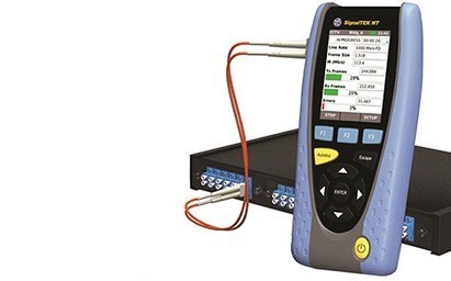
Transmission testing requires the two handsets that make up the test system to communicate on at least Layers 1 and 2 of the OSI model. Some testers can operate up to Layer 4 when required for specific applications.
To measure the parameters defined in 802.3ab, a test system must generate Ethernet frames, transmit them across a cabling link or through a network, and measure the number of frames that are corrupt and dropped from the data transmission over a specified period of time. This needs to occur in both directions simultaneously, which means the test device must have active components at both ends of the cabling link or network being tested. The results of the test indicate whether the link supports transmission of data at the rate at which it is designed.
Phases of Transmission Testing
Transmission testing is a process that can be complicated, especially when testing between locations across the Internet. Because this article is comparing transmission testers to qualifiers, it will be limited to LAN testing.
Step 1 – Physical media connection (Layer 1): The handsets are connected at either end of the link being tested. At this point the two handsets have established an electrical connection across the cable (or optical when testing fiber) to perform basic tests. On copper, the tester will be able to perform a wiremap test to check for termination faults and damage to the cable. The tester may also measure the length of the cable. When connected to the cable, the RJ45 link LEDs will light, indicating the electrical connection has been established. The link “speed” depends on the capability of the transmission tester. A Gigabit tester should be at 1-Gbit/sec when connected to a cable with all four pairs properly terminated. The indicators are usually present when testing fiber. The LEDs on the fiber port of the equipment will light and stay on when they detect a signal at the input port. This helps when troubleshooting polarity (crossing transmit/receive) problems.
Some might mistake the 1-Gbit/sec link as proof that the cable will support 1-Gbit/sec data transmission. Not true. The auto-negotiation process is an electrical “handshake” between the devices. No data is transmitted during the link process.
There are qualifiers on the market that use the auto-negotiation process alone to qualify a cable and generate a “Pass” report. This is very misleading because, for example, a short link of Category 3 cable with Category 5e connectors, or even a Category 5e cable with a split-pair fault will often link at 1 Gbit/sec, yet will completely fail to transmit data, or will transmit with a very high error rate.
Step 2 – Linking (Layer 2): Each handset broadcasts its unique MAC address and listens for the MAC address of its partner. When connected to a common cable, they establish a Layer 2 link and are prepared to transmit data frames across the cable.
In addition to linking on a single cable run, some testers may have the capability to link across the LAN. Each handset will broadcast its MAC address to the LAN and the network switches will learn a path to link the two handsets, regardless of location, as long as they are on the same network. This system allows testing of every section of cabling, and each switch and media converter between the handsets. Even when a handset is connected to an RJ45 port in one building and the other handset is connected to a fiber-optic port of a switch in a different location, they will still link to each other.
It is worth noting that typical qualifiers are not active network devices (they do not have an Ethernet PHY) and do not have this capability. Their connection stops at Layer 1.
Step 3 – Data transmission test (Layer 2): The data transmission test is where the proof of performance lies. The tester creates Ethernet frames packed full of data and sends them out its network port to begin the test. Each frame has the source and destination MAC addresses of the two test handsets. This is a full-duplex operation, meaning each handset is performing this process at the same time, transmitting data in both directions on the cable simultaneously.
The test system will transmit continuous data at a specified rate for a specific amount of time. The IEEE standard provides a ratio of good to bad frames and the tester will send the minimum amount of data required to prove whether or not the system meets this performance requirement. Users can also choose to have the test run for a number of minutes or hours, which is helpful when troubleshooting network problems that happen at random times.
If the testers are connected to each other by a single cabling link, those are the only components under test. However, if connected to a live LAN the data frames will be sent to the nearest switch and from that point on, it is the responsibility of the network to transport the test frames between the two handsets. This is a complete test of the data transmission path between any two points on a LAN, proving that all the network components between the two testers are functional. This is an important function qualifiers cannot perform.
Advantages of Transmission Testers
A transmission tester checks more than just the physical connection between two points to infer that the cable is capable of supporting error-free transmission of data. It establishes a complete electrical and data link connection to the cabling or LAN and making pass/fail determinations of performance by transmitting and checking Ethernet frames. This is a direct measurement of the flow of data versus qualifiers that perform measurements that are not traceable back to any standard to make a pass/fail determination.
When testing cable and networking components on an Ethernet LAN, the best way to be certain it meets performance is to perform tests that measure the physical, electrical and data transmission capabilities of those components to the requirements of the IEEE 802.3 standard that defines Ethernet.


